
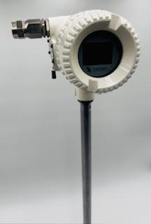
OXFTM Series Thermal Mass Flowmeter measures the gas mass flow base on thermal diffusion theory. It has two filmed RTDs as its sensors, one of which sense the velocity of the gas flow (RH) and the other one will detect the temperature shift of the gas flow (RMG). When the two RTD are in the gas flow ,the RH will be heated while the RMG will sense the temperature changing of the gas flow. More heat will be taken away as the velocity of the gas flow increasing, so the temperature on RH will decline.
| Parameter | Specification |
|---|---|
| Flow Range | 0.25 to 150 SFPS (Standard Feet Per Second) |
| Accuracy | ±1% of reading ±0.5% of full scale |
| Repeatability | ±0.2% of full scale |
| Turn-down Ratio | Up to 100:1 |
| Operating Temperature | -40°C to +100°C |
| Pressure Rating | Up to 300 psig (standard), higher options available |
| Power Supply | 24 VDC or loop-powered |
| Output Signal | 4–20 mA, HART, Modbus RTU |
| Enclosure | NEMA 4X/IP66 |
| Sensor Material | 316L Stainless Steel |
| Mounting | Inline or insertion type |
| Display | Optional local display with keypad |
| Probe | H | L |
|---|---|---|
| 11.42″ (290 mm) | 17.07″ | 10.06″ |
| 17.32″ (440 mm) | 22.97″ | 15.97″ |
| 27.12″ (690 mm) | 32.82″ | 25.81″ |
| 39.37″ (1000 mm) | 45.02″ | 38.01″ |
| 59.06″ (1500 mm) | 64.71″ | 57.70″ |
| MAX PIPE SIZE THAT EACH PROBE CAN ADAPT TO | |||||
|---|---|---|---|---|---|
| Probe length | 290mm | 440mm | 690mm | 1000mm | 1500mm |
| T < 50 dgr C | DN150 | DN450 | DN900 | DN1500 | DN2500 |
| 50 °C < T < 150 °C | I | DNl00 | DN600 | DN1200 | DN2200 |
| 150 °C < T < 250 °C | I | I | DN400 | DNl000 | DN2000 |
| 250 °C < T < 450 °C | I | I | DN300 | DN600 | DNl000 |
| T < 122 °F | 6″ | 18″ | 36″ | 60″ | 100″ |
| 122 °F < T < 302 °F | I | 4″ | 24″ | 48″ | 88″ |
| 302 °F < T < 482 °F | I | I | 16″ | 40″ | 80″ |
| 482 °F < T < 842 °F | I | I | 12″ | 24″ | 40″ |


| Pipe size (mm) | Pipe size (inch) | Option 1 (0.3-30 Nm/s) | Standard (0.6-60 Nm/s) | Option 2 (0.9-90 Nm/s) | Option 3 (1.2-120 Nm/s) | ||||
|---|---|---|---|---|---|---|---|---|---|
| Min flow Nm³/hr | Max flow Nm³/hr | Min flow Nm³/hr | Max flow Nm³/hr | Min flow Nm³/hr | Max flow Nm³/hr | Min flow Nm³/hr | Max flow Nm³/hr | ||
| 25 | 1″ | 0.53 | 53 | 1.05 | 105.9 | 1.58 | 158.8 | 2.11 | 211.8 |
| 32 | 1¼” | 0.87 | 86.7 | 1.73 | 173.5 | 2.6 | 260.3 | 3.47 | 347.1 |
| 40 | 1½” | 1.36 | 135.6 | 2.71 | 271.1 | 4.06 | 406.7 | 5.42 | 542.3 |
| 50 | 2″ | 2.12 | 211.9 | 4.23 | 423.7 | 6.35 | 635.5 | 8.47 | 847.4 |
| 65 | 2½” | 3.58 | 358.1 | 7.1 | 716.1 | 10.7 | 1074.1 | 14.3 | 1432.2 |
| 80 | 3″ | 5.42 | 542.3 | 10.8 | 1084.7 | 16.2 | 1627.1 | 21.6 | 2169.4 |
| 100 | 4″ | 8.47 | 847.5 | 16.9 | 1694.9 | 25.4 | 2542.3 | 33.8 | 3389.8 |
| 125 | 5″ | 13.2 | 1324.2 | 26.4 | 2648.3 | 39.7 | 3972.4 | 52.9 | 5296.6 |
| 150 | 6″ | 19.1 | 1906.8 | 38.1 | 3813.5 | 57.2 | 5720.3 | 76.2 | 7627.1 |
| 200 | 8″ | 33.9 | 3389.8 | 67.7 | 6779.6 | 101.6 | 10169.4 | 135.5 | 13559.3 |
| 250 | 10″ | 53 | 5296.6 | 105.9 | 10593.2 | 158.8 | 15889.8 | 211.8 | 21186.4 |
| 300 | 12″ | 76.3 | 7627.1 | 152.5 | 15254.2 | 228.8 | 22881.3 | 305 | 30508.4 |
The standard model number is usually OXFTM-1-2-12-1-N-T-M-N-1-1-XXXX,
Please reference to the table below for what the model codes stand for.
| Section | Code | Description | Type |
|---|---|---|---|
| General model | OXFTM | Standard | |
| Air/nitrogen | Standard | ||
| 2 Fluid type | 2 | Oxygen (sensor will be degreased) | Option |
| 3 | Other (Please advise gas composition) | Option | |
| 0.3-30 Nm/s | Option | ||
| 2 | 0.6-60 Nm/s | Standard | |
| 3 Measurement | 3 | 0.9-90 Nm/s | Option |
| range | 4 | 1.2-120 Nm/s | Option |
| 5 | 1.5-150 Nm/s | Option | |
| 6 | 1.8-180 Nm/s | Option | |
| 11 | Insertion type with 290mm probe | Option | |
| 12 | Insertion type with 440mm probe | Standard | |
| 13 | Insertion type with 690mm probe | Option | |
| 14 | Insertion type with 1000mm probe | Option | |
| 15 | Insertion type with 1500mm probe | Option | |
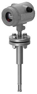
| Fl | Flanged insertion type up to 25 barG (362 psiG) | Option | |
| F2 | Flanged insertion type up to 40 barG (580 psiG) | Option | |
| F2 | Flanged insertion type up to 63 barG (913 psiG) | Option | |
| 4 Process | Dl | Flanged DIN PN16 up to 16 barG (232 psiG) (DN15-DN300) | Option |
| connection | D2 | Flanged DIN PN25 up to 25 barG (362 psiG) (DN15-DN300) | Option |
| D3 | Flanged DIN PN40 up to 40 barG (580 psiG) (DN15-DN300) | Option | |
| D4 | Flanged DIN PN63 up to 63 barG (913 psiG) (DN15-DN300) | Option | |
| Cl | Flanged ANSI CL150 up to 16 barG (232 psiG) (0.5 inch–12 inch) | Option | |
| C2 | Flanged ANSI CL300 up to 40 barG (580 psiG) (0.5 inch–12 inch) | Option | |
| C3 | Flanged ANSI CL400 up to 63 barG (913 psiG) (0.5 inch–12 inch) | Option | |
| Jl | JIS 10K up to 16 barG (232 psiG) (DN15–DN300) | Option | |
| J2 | JIS 20K up to 40 barG (580 psiG) (DN15–DN300) | Option | |
| J3 | JIS 30K up to 63 barG (913 psiG) (DN15–DN300) | Option | |
| 5 Wetted part | 316ss sensor with 304ss wetted parts | Standard | |
| material | 2 | 316ss sensor with 316ss wetted parts | Option |
| Medium temp | N | < 150°C | Standard |
| 6 range | Q | < 250°C | Option |
| H | < 450°C (please select remote display also) | Option | |
| 7 Transmitter | T | Integral | Standard |
| R | Remote | Option | |
| 8 Cable grinder | M | M20 x 1.5 | Standard |
| N | NPT 1/2 | Option | |
| 9 Ex-proof | N | No Ex-proof | Standard |
| NEPSI Ex d IIC T3 Gb | Option | ||
| pulse/frequency + 4-20mA + RS485 + Bluetooth | Standard | ||
| 2 | pulse/frequency + 4-20mA @ HART + Bluetooth | Option | |
| 11 Power supply | 13.5–42VDC | Standard | |
| 2 | 13.5–42VDC with 85–265VAC 50/60Hz power converter | Option | |
| 12 Pipe size | xxxx | Please use 4-digit pipe size, such as DN50=0050, DN300=0300 | xxxx |